Toyota Yaris XP130 Fuses: Complete Guide 2010-2020
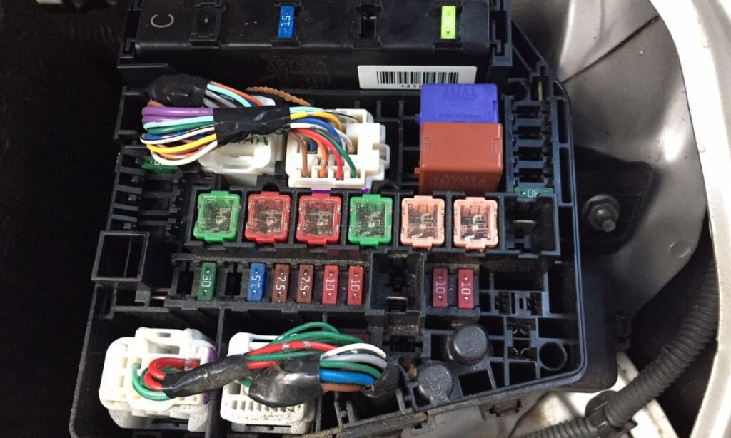
The Toyota Yaris XP130 (2010–2020) uses multiple fuse boxes to protect its electrical circuits from overloads and short circuits. Knowing the exact location, amperage, and function of every fuse is essential for diagnosing electrical faults, replacing blown fuses correctly, and avoiding costly dealer visits. This guide covers every fuse in every box of the Yaris XP130, including engine bay, interior, and relay block details, based on official Toyota wiring documentation.
Fuse Box Locations – Toyota Yaris XP130
The XP130 Yaris has three main fuse/relay locations:
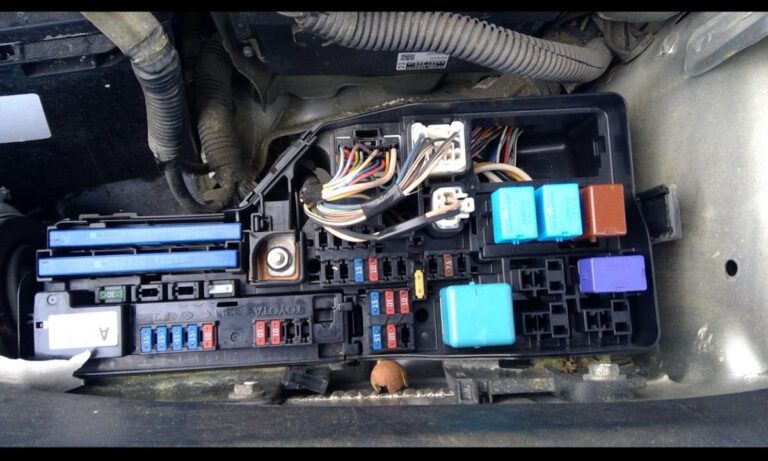
- Engine compartment fuse box – located on the left side of the engine bay, near the battery
- Instrument panel fuse box (interior) – located under the dashboard on the driver’s side, behind a removable cover
- Relay block / multiplex network control unit – integrated within the engine bay box on most variants
Engine Compartment Fuse Box – Full Fuse List
This box handles high-current circuits critical to engine and safety systems. Always disconnect the battery before replacing fuses in this block on circuits marked ALT or EFI.
- ALT – 120A – Alternator charge circuit
- AM1 – 80A – Main power supply to ignition switch
- AM2 – 60A – Secondary main power supply
- EFI – 30A – Engine management / fuel injection system
- ABS NO.1 – 30A – ABS actuator motor
- ABS NO.2 – 15A – ABS ECU and solenoid valves
- HTR – 30A – Heater blower motor
- DEF – 25A – Rear window defroster
- ST – 7.5A – Starter relay circuit
- HORN – 10A – Horn relay and horn assembly
- DOME – 10A – Interior dome/cabin light supply
- TAIL – 15A – Tail lights, number plate lights
- HEAD LH – 15A – Left headlight (low beam)
- HEAD RH – 15A – Right headlight (low beam)
- FOG – 15A – Front fog lights (where fitted)
- SPARE – 10A – Unassigned spare fuse
- RAD FAN – 30A – Radiator cooling fan motor
- CONDENSER FAN – 20A – A/C condenser fan motor
- IGN – 7.5A – Ignition switch signal circuit
- ECU-IG – 10A – Engine ECU ignition power supply
- INJ – 15A – Fuel injectors
- ETCS – 10A – Electronic throttle control system
- VSC – 10A – Vehicle stability control module
- CDS FAN – 10A – Condenser fan relay control
Interior / Instrument Panel Fuse Box – Full Fuse List
The interior fuse box is accessible by opening the driver’s door and removing the cover panel at the left end of the dashboard. Each circuit below corresponds to exact Toyota XP130 factory assignments:
- 1 – 15A – Power windows front left
- 2 – 15A – Power windows front right
- 3 – 10A – Door locks / central locking system
- 4 – 10A – Combination meter / instrument cluster
- 5 – 10A – Radio / audio head unit
- 6 – 15A – Cigarette lighter / accessory socket
- 7 – 10A – Reverse lights / back-up lamp circuit
- 8 – 10A – Stop lamps (brake lights)
- 9 – 7.5A – Turn signal / hazard warning system
- 10 – 10A – Daytime running lights (DRL) where fitted
- 11 – 10A – A/C amplifier and climate control panel
- 12 – 7.5A – SRS airbag ECU
- 13 – 7.5A – Body ECU / multiplex network
- 14 – 10A – Combination switch (steering column stalk)
- 15 – 7.5A – Keyless entry / smart entry system
- 16 – 10A – Interior lights, courtesy lamps, map reading lights
- 17 – 15A – Heated rear window relay control
- 18 – 10A – OBD-II diagnostic port power
- 19 – 10A – Windscreen wiper and washer motor
- 20 – 10A – Instrument illumination / dimmer circuit
- 21 – 7.5A – Immobiliser / transponder key ECU
- 22 – 10A – Speed sensor / vehicle speed signal
- 23 – 15A – Rear wiper and washer (5-door models)
- 24 – 10A – Mirror heaters and electric mirror adjustment
- 25 – 10A – Fuel pump relay control circuit
Important Fuse Replacement Guidelines for XP130
- Always use standard blade-type (ATC/ATO) fuses for interior positions and maxi blade fuses for engine bay high-current positions
- Never replace a fuse with a higher amperage rating – this can cause wiring fires
- If a fuse blows repeatedly, the cause is an underlying short circuit or overloaded component – do not keep replacing without diagnosis
- The XP130 uses mini blade (low-profile) fuses in the interior box on later facelift models (2017–2020) – check your specific fuse type before purchasing replacements
- A fuse puller tool is stored inside the engine bay fuse box lid on most XP130 examples
- After any fuse replacement, use a multimeter or test light to confirm circuit continuity before reassembling covers
- The SRS airbag fuse (7.5A, position 12) should only be handled with the ignition off and a minimum 90-second wait after disconnecting the battery
Common Electrical Faults and Related Fuses – Yaris XP130
- No interior lights or dome light – check DOME fuse (10A, engine bay) and fuse 16 (10A, interior box)
- Radio/audio not working – check fuse 5 (10A, interior) and confirm ACC power on ignition switch
- Brake lights not working – inspect fuse 8 (10A, interior) before checking stop-lamp switch
- Power windows inoperative – check fuses 1 and 2 (15A each) and the main HTR 30A relay
- Fuel pump failure to prime – fuse 25 (10A, interior) controls the fuel pump relay signal
- ABS warning light on with no braking assist – verify ABS NO.1 (30A) and ABS NO.2 (15A) in engine bay box
- Heater fan not operating at any speed – HTR fuse (30A, engine bay) is the first check point
- OBD scanner not powering on – fuse 18 (10A, interior box) powers the OBD-II port directly