Chevrolet Cruze fuse box diagrams: Full schematics for fll generations
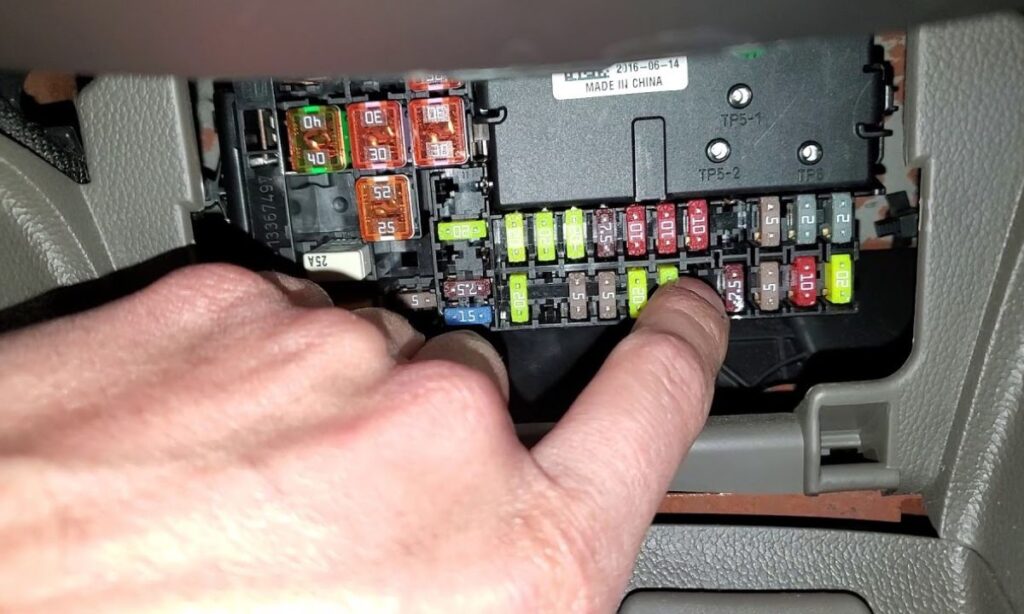
The Chevrolet Cruze, a popular compact car produced from 2008 to 2019, features two main fuse boxes: one in the interior cabin and another under the hood in the engine compartment. These protect electrical circuits from overloads and shorts. Fuse layouts vary by generation, with the first generation (J300, 2008-2016) and second generation (J400, 2016-2019) having distinct configurations. Always consult your owner’s manual for specifics, and use the correct amperage when replacing fuses to avoid damage.
Understanding these diagrams helps diagnose issues like non-working lights, radio failures, or power accessory problems. We’ll cover locations, fuse assignments, and relays for both generations.
First generation (J300, 2008-2016)
This generation includes models from 2008 through 2016, with fuse boxes designed for straightforward access.
Interior fuse box location and diagram
The instrument panel fuse box is on the driver’s side, behind a cover to the left of the steering wheel. Remove the cover for access.
Key fuses and their functions:
- 1: Mobile Telephone Control Module (10A)
- 3: Body Control Module (25A)
- 4: Radio (20A)
- 5: Parking Assist Control Module, Power Sounder, Multifunction Switch – Centre Console, Display (7.5A)
- 6: Cigar Lighter – Front (20A)
- 7: Accessory Power Outlet – Centre Console 1/2 (20A)
- 8: Body Control Module (30A)
- 9: Body Control Module (30A)
- 10: Body Control Module (30A)
- 11: Blower Motor Control Module (40A)
- 13: Heated Seat Control Module (25A)
- 14: Data Link Connector, Oil Feeding Connector (7.5A)
- 15: Inflatable Restraint Sensing and Diagnostic Module (10A)
- 16: Rear Compartment Lid Release Relay (10A)
- 17: HVAC Control Module / HVAC Control Assembly (15A)
- 21: Instrument Cluster (15A)
- 22: Ignition Switch / Remote Control Door Lock Receiver (2A)
- 23: Body Control Module (20A)
- 24: Body Control Module (20A)
- 25: Steering Column Lock Control Module (20A)
Relays in the interior box:
- 1: Rear Compartment Lid Release
- 2: Logistic Mode Relay 1
- 3: Auxiliary Power Relay
Note: Unused slots are marked as “Not Used” and should remain empty.
Engine compartment fuse box location and diagram
Located under the hood near the battery, this box has a removable cover for inspection.
Key fuses and their functions:
- 1: Transmission Control Module (15A)
- 2: Engine Control Module (15A)
- 5: Transmission Control Module, Engine Control Module, Mass Air Flow/Intake Air Temperature Sensor, Output Speed Sensor (15A)
- 6: Windshield Wiper Relays (30A)
- 8: Fuel injectors (15A)
- 9: Ignition Coil, Fuel Injectors (15A)
- 10: Engine Control Module, Output Speed Sensor (15A)
- 11: Heated Oxygen Sensors (10A)
- 12: Starter Motor (30A)
- 13: Evaporative Emission (EVAP) Canister Vent Solenoid Valve (7.5A)
- 16: Air Quality Sensor (7.5A)
- 17: Inflatable Restraint Sensing and Diagnostic Module (5A)
- 18: Fuel Pump Control Module (10A)
- 20: Fuel Pump Relay (20A)
- 21: Windows Motors, Front Door (30A)
- 24: Windows Motors, Front Door (30A)
- 26: Electronic Brake Control Module (EBCM) (40A)
- 27: Remote Control Door Lock Receiver (30A)
- 28: Rear Demister Grid (40A)
- 30: Electronic Brake Control Module (EBCM) (15A)
- 31: Body Control Module (20A)
- 32: Body Control Module (20A)
- 33: Heated Seat Control Module (30A)
- 34: Sunroof Control Module (25A)
- 35: Audio Amplifier (30A)
- 37: Headlamp – Right Main beam (10A)
- 38: Headlamp – Left Main beam (10A)
- 42: Cooling Fan Relays, Cooling Fan Motor (20/30A)
- 45: Cooling Fan High Speed Relay, Cooling Fan Motor (30/40A)
- 46: Cooling Fan Relays (10A)
- 47: Heated Oxygen Sensors, Throttle Body (10A)
- 48: Fog Lights, Front (15A)
- 51: Horn (15A)
- 52: Instrument Cluster (5A)
- 53: Inside Rearview Mirror (10A)
- 54: Headlamp Switch, Electrical Auxiliary Heater, HVAC Control Module (5A)
- 55: Window Switches, Front, Mirror Switch (7.5A)
- 56: Windscreen Washer Pump (15A)
- 57: Steering Column Lock Control Module (15A)
- 59: Fuel Heater (30A)
- 60: Outside Rearview Mirrors (7.5A)
- 62: A/C Compressor Clutch Relay, A/C Compressor Clutch (10A)
- 64: Inflatable Restraint Sensing and Diagnostic Module (5A)
- 67: Fuel Pump Control Module (20A)
- 69: Body Control Module (5A)
- 70: Rain Sensor (5A)
Relays in the engine compartment:
- 1: A/C Compressor Clutch
- 2: Starter
- 3: Cooling Fan
- 4: Windshield Wiper Speed Control
- 5: Windshield Wiper
- 7: Powertrain
- 8: Fuel Pump
- 9: Cooling Fan Medium Speed 1
- 10: Cooling Fan Medium Speed 2
- 12: Cooling Fan Speed Control
- 13: Cooling Fan High Speed Relay
- 15: Ignition Main Relay
- 16: Fuel Heater Relay
- 17: Rear Window Defogger
Non-serviceable relays (PCB): Horn Relay, Windscreen Washer Pump Relay, Front Fog Lamp Relay, Headlamp High Beam Relay.
Second generation (J400, 2016-2019)
The later models feature updated electrical systems, with some variations by year.
Interior fuse box location and diagram
Situated behind a cover in the central console under the HVAC controls. Pull the top, remove the lower edge, and take off the cover.
Key fuses and their functions (noting year-specific differences):
- F1: Right rear power window (2017 only)
- F2: Blower
- F3: Driver power seat
- F4: Front power outlet
- F5: Right front power window (2017 only)
- F6: Front power windows (2016, 2018, 2019) / Front left power window (2017)
- F7: ABS valves
- F8: Cyber gateway module (CGM)
- F9: Body control module 8
- F10: Rear power windows (2016, 2018, 2019) / Left rear power window (2017)
- F11: Sunroof
- F12: Body control module 4
- F13: Heated front seats
- F14: Exterior mirrors/Lane keep assist/ High-beam headlamp auto control
- F15: Body control module 1
- F16: Body control module 7
- F17: Body control module 6
- F18: Body control module 3
- F19: Data link connector
- F20: Airbag
- F21: A/C
- F22: Trunk release
- F23: Passive entry/ Passive start
- F24: Right front child presence detection (2016-2017) / Passenger sensing system (2018) / AOS system (2019)
- F25: Steering wheel switch illumination
- F26: Ignition switch
- F27: Body control module 2
- F28: Amplifier
- F29: USB charge (2018-2019)
- F30: Shift lever illumination
- F31: Rear wiper
- F32: Transmission control module (with Stop/Start, 2016-2018) / Virtual key system (2019)
- F33: Mobile phone wireless charging/ DC AC converter
- F34: Parking assist/Side blind zone alert/ Infotainment/USB
- F35: OnStar
- F36: Display/Cluster
- F37: Radio
No relays listed in the interior for this generation.
Engine compartment fuse box location and diagram
Under the hood, near the front left side, with a clip-on cover.
Key fuses and their functions (with year notes):
- F01: Starter
- F02: Starter
- F03: O2 sensor
- F04: Engine control module
- F05: Engine functions (2016-2018) / Aero shutter/ Fuel flex (2019)
- F06: Transmission control module
- F08: Engine control module
- F09: A/C
- F10: Canister vent
- F11: Heated seats
- F12: CGM module
- F13: After boil pump/ Heated steering wheel (2016-2018) / Aero shutter/Fuel flex (2019)
- F14: Diesel NOx/CVT8 transmission
- F15: O2 sensor
- F16: Fuel injection
- F17: Fuel injection
- F18: Diesel NOx
- F19: Diesel NOx (2016-2018) / Diesel NOx/Coolant motor (2019)
- F21: Electric parking brake (2016-2018) / DC/AC converter (2019)
- F22: ABS system
- F23: Windshield washer/ Rear windows
- F25: Diesel fuel heating/ Secondary air induction (2016-2018) / Diesel fuel heating (2019)
- F26: Transmission
- F29: Rear window defogger
- F30: Mirror defogger
- F32: Display LED/DC DC converter/FPPM/ Electrical heater/A/C module
- F33: Anti-theft warning horn
- F34: Horn
- F35: Trunk power outlet
- F36: Right high-beam headlamp
- F37: Left high-beam headlamp
- F39: Front fog lamps
- F40: AIR solenoid
- F41: Switchable water pump/Water in fuel sensor
- F42: Manual headlamp leveling
- F43: Fuel pump
- F44: Interior rearview mirror/Rear vision camera/Trailer
- F45: Heated steering wheel
- F46: Cluster
- F47: Steering column lock
- F48: Rear wiper
- F52: Engine/Transmission control module
- F54: Windshield wiper
- F55: Diesel NOx (2016-2018)
- F56: Aeroshutter (2016-2018)
Relays:
- K01: Starter
- K02: A/C control
- K03: Engine functions
- K04: CVT8 transmission (2016-2017)
- K05: Starter
- K06: Diesel fuel heating/ Secondary air induction
- K07: Right low-beam headlamp/Right daytime running lamp
- K08: Transmission
- K09: Diesel NOx
- K10: Fuel pump
- K12: High-beam headlamps
- K13: Left daytime running lamp/Left low-beam headlamp
- K14: Run/Crank
- K15: Mirror defogger/Rear window defogger/ Anti-theft warning sensor
- K16: Horn/Dual horn
- K17: Diesel NOx
- K18: Front fog lamps
- K19: After boil pump/ Heated steering wheel
- K20: Anti-theft warning horn
- K21: Rear window washer
- K22: Front window washer
- K23: Rear window wiper
Additional fuses near the battery (2018-2019 only):
- 1: Transmission control module (AT only, 2018) / Engine control module (2019)
- 2: Fuel pump
- 3: Engine control module (2018) / Transmission control module (2019)
- 4: Power supply
These diagrams provide a comprehensive reference for troubleshooting. If a fuse blows repeatedly, check for underlying electrical faults like shorts or faulty components. For safety, disconnect the battery before working on fuses, and use tools like a fuse puller for easy removal. This knowledge empowers Cruze owners to handle basic electrical diagnostics effectively.