Toyota Yaris XP90 Fuses 2005-2011: Complete Guide

The Toyota Yaris XP90 (second generation, 2005–2011) uses two main fuse boxes to protect every electrical circuit in the vehicle. Understanding the exact location, amperage, and function of each fuse is essential for diagnosing electrical faults, replacing blown fuses safely, and avoiding damage to sensitive components. This guide covers every fuse in both the interior cabin fuse box and the engine compartment relay/fuse block, including all known variants across the XP90 production run.
Fuse Box Locations on the Toyota Yaris XP90
The Yaris XP90 has two fuse boxes:
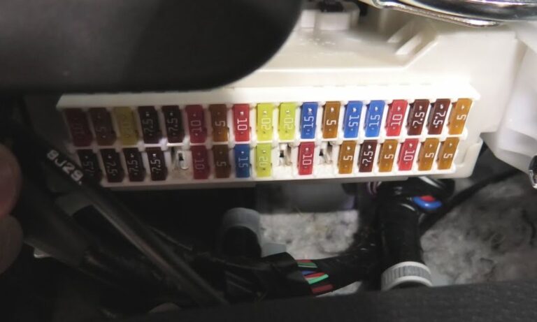
- Interior fuse box (cabin) – Located on the driver’s side lower dashboard, behind a removable cover panel. Accessible without tools by pulling the panel toward you.
- Engine compartment fuse and relay box – Located in the engine bay on the left side (driver’s side in LHD markets), next to the battery. Secured with a clip-on lid marked with a fuse layout diagram.
How to Identify a Blown Fuse
- Remove the fuse using the plastic fuse puller stored inside the cabin fuse box lid.
- Hold the fuse up to a light source – a broken metal strip inside indicates a blown fuse.
- Always replace with the exact same amperage rating. Never fit a higher-rated fuse.
- If a fuse blows repeatedly, an underlying short circuit must be diagnosed before replacing again.
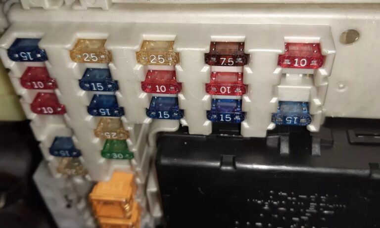
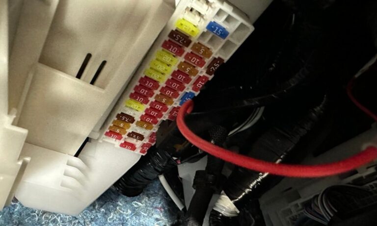
Interior Cabin Fuse Box – Complete Fuse List
- 1 – 7.5A – Gauge cluster, instrument panel illumination
- 2 – 10A – Hazard warning lights
- 3 – 10A – Dome light, interior lamp, map light
- 4 – 15A – Cigarette lighter / accessory socket
- 5 – 7.5A – ECU (Engine Control Unit) back-up power
- 6 – 7.5A – Multiplex communication system (body ECU)
- 7 – 10A – Power windows (if equipped)
- 8 – 10A – Door lock actuators / central locking
- 9 – 7.5A – Combination meter, speedometer
- 10 – 10A – Air conditioning control panel
- 11 – 15A – Heater blower motor
- 12 – 10A – Audio system / radio
- 13 – 7.5A – SRS airbag system ECU
- 14 – 10A – ABS/VSC control unit (models with ABS)
- 15 – 10A – Stop/brake lights
- 16 – 15A – Windscreen wiper motor
- 17 – 10A – Turn signal lights, side markers
- 18 – 7.5A – Reverse lights, back-up lamps
- 19 – 10A – Front and rear washer pump motor
- 20 – 10A – Rear demister / heated rear window
- 21 – 15A – OBD-II diagnostic port power supply
- 22 – 10A – Immobiliser / transponder key ECU
- 23 – 7.5A – Power mirrors (if equipped)
- 24 – 10A – Tail lights, number plate lights, parking lights
Engine Compartment Fuse and Relay Box – Complete Fuse List
- EFI 15A – Electronic Fuel Injection main relay, fuel pump relay power
- IGN 7.5A – Ignition switch circuit, coil packs
- AM2 10A – Ignition key-on accessories (second accessory line)
- AM1 40A (fusible link) – Main battery feed to interior fuse box
- ALT-S 7.5A – Alternator sensing circuit, charge warning light
- ABS 30A – ABS hydraulic control unit motor (ABS-equipped models)
- ABS-2 7.5A – ABS ECU logic power supply
- HTR 30A – Heater and air conditioning blower high-current feed
- HORN 10A – Horn relay and horn
- FOG 15A – Front fog lights (if equipped)
- HEAD LH 15A – Left-side headlight (low and high beam)
- HEAD RH 15A – Right-side headlight (low and high beam)
- TAIL 15A – Tail lights, rear position lamps, dashboard illumination feed
- RAD FAN 30A – Radiator cooling fan motor
- MAIN 60A (fusible link) – Primary main fusible link from battery positive terminal
- STARTER 7.5A – Starter motor relay control circuit
- WIPER 20A – Front wiper motor high-current supply
- FUEL PMP 10A – Fuel pump relay output to fuel pump
- DCDC 10A – DC-DC converter (models with specific electrical packages)
- INJ 10A – Fuel injectors power supply
- ST 7.5A – Starter relay signal feed
Relay Locations in the Engine Compartment Box
- Main relay (EFI relay) – Controls fuel pump and injector power on engine start
- Cooling fan relay – Activates radiator fan based on coolant temperature signal
- A/C relay – Engages compressor clutch when A/C is requested
- Starter relay – High-current relay for starter motor engagement
- Horn relay – Isolates horn button from high-current horn circuit
Fuse Ratings and Types Used in the XP90 Yaris
- The XP90 Yaris uses standard blade fuses (ATO/ATC type) throughout both fuse boxes.
- Mini blade fuses (ATM type) are used in select positions in the cabin fuse box on some regional variants.
- Fusible links are large-format fuses located in the engine bay box – never replace fusible links with standard blade fuses.
- Spare fuses (7.5A and 10A) are often stored inside the cabin fuse box lid in a dedicated holder.
Common Electrical Problems Related to Fuses on the Yaris XP90
- Radio not working – Check fuse 12 (10A) in the cabin box first.
- Brake lights inoperative – Fuse 15 (10A) in the cabin box; also check the brake light switch.
- Wipers not working – Check fuse 16 (15A) cabin and WIPER 20A in engine bay box.
- Central locking failure – Fuse 8 (10A) in cabin box.
- Engine cranks but will not start – Check EFI 15A and FUEL PMP 10A in engine bay; also INJ 10A.
- No interior lights – Fuse 3 (10A) in cabin box.
- ABS warning light on, ABS inactive – Check ABS 30A and ABS-2 7.5A in engine bay box.
- Air conditioning not blowing – Check HTR 30A in engine bay and fuse 11 (15A) in cabin box.