Ford Mustang fuse box diagrams: Complete & detailed schemes for all generations
The Ford Mustang’s electrical system has grown vastly more complex over six decades. A single blown fuse can disable headlights, power windows, the fuel pump, ABS, or even the starter. Below are the most complete fuse box diagrams available for every major generation, compiled from official Ford service data, owner manuals, LMR technical guides, Mustang7G forums, and verified sources like startmycar.com and mustangspecs.com.
Important notes for all generations:
- Always replace fuses with the exact amperage and type.
- Disconnect the battery before working on high-current fuses.
- Modern Mustangs (2015+) may require a scan tool after fuse replacement to clear codes.
- Diagrams can vary slightly by trim (V6/GT/EcoBoost/Dark Horse/GT500), transmission, convertible vs. coupe, and options. Always verify with your VIN-specific owner’s manual.
1st Generation (1964–1973) – Classic fuse panel
Location: Under the dash on the driver’s side, left of the steering column.
Many circuits use thermal circuit breakers (C.B.) or glass fuses (SFE/AGC/AGX). No under-hood box.
Full Fuse Chart 1964–1973 (every circuit listed):
| Purpose | Location | Fuse Type | Applies To Years |
|---|---|---|---|
| Tail, stop, park, license, horn, side markers | Light switch | 15A Ckt breaker | All 1964–1973 |
| Air conditioning – Integrated | Ignition switch | 25A C.B. | 1964–1967 |
| Air conditioning – Integrated | — | 30A SFE | 1968–1973 |
| Air Conditioner – Economy | Inline from Ign. Sw | 15A AGC | 1964–1967 |
| Heater with A/C | Fuse panel | 14A SFE | 1968–1973 |
| Heater W/o A/C | Fuse panel | 30A AGX | All 1964–1973 |
| Backup lights | Fuse panel | 14A SFE / 14A AGC / 20A SFE | 1964–1967 (14 SFE), 1968+ (14 AGC / 20 SFE) |
| Turn Signals | Turn signal flasher | 20A SFE | All |
| Radio | Fuse panel | 14A SFE (1964–1968) / 15A SFE (1969+) | All |
| Courtesy Light | Fuse panel | 7.5A SFE (early) / 14A SFE (1969+) | All |
| Cigar Lighter | Fuse panel | 14A SFE / 20A SFE | Varies by year |
| Console – Auto Trans. Light | — | 14A SFE | 1964–1968 |
| Clock | Fuse panel | 7.5A SFE / 14A SFE | All |
| Convertible top | Fuse link / panel | 20A SFE / 15A C.B. | Varies |
| Defogger | Inline | 7.5A SFE | 1968+ |
| Door ajar and Seat belts | — | 7.5A SFE / 20A SFE | Varies |
| Dome & Map | Fuse panel | 7.5A SFE / 14A SFE | All |
| Emergency Warning flasher | Fuse panel | 20A SFE | All |
| Engine compartment light | Fuse panel | 20A SFE | 1968+ |
| Fog Lights | Fuse panel | 10A C.B. | 1968–1970 |
| Intermittent WS Wipers | — | 7A C.B. | 1971–1973 |
| Horns (via headlight switch) | — | 15A C.B. | 1969+ |
| Speed Control | Inline | 7.5A SFE / 20A SFE | Varies |
| Parking brake warning | Inline | 7.5A SFE / 15A SFE | Varies |
| Power windows | Fuse panel | 20A SFE | 1971–1973 |
2nd & 3rd Generations – Fox body (1979–1993)
Location: Interior fuse panel – driver’s side kick panel.
Under-hood power distribution box on EFI models (1986+).
1979–1982 Full Interior Fuse Panel
| Position | Amperage | Protected Circuits |
|---|---|---|
| 1 | 5A | Illumination lamps, cluster, clock, radio, heater controls (varies by year) |
| 2 | 10A | Warning lights, oil pressure, temperature, seat belt, tachometer |
| 4 | 20A | Horn, cigar lighter, console clock |
| 5 | 20A | Horn, cigar lighter (1979 specific) |
| 7 | 15A | Courtesy lights, dome, glove box, luggage compartment |
| 8 | 20A/15A | Hazard, stop lights, exterior lights |
| 10 | 15A | Radio |
| 11 | 25A/20A | A/C clutch, heated backlight, speed control |
| 12 | 6A C.B. | Windshield wiper/washer |
| 13 | 5A/20A/15A | Stop lamps, hazard (later years) |
| 14 | 30A/15A | Heater / A/C system |
| 15 | 20A/15A/30A | Turn signals, backup lights, heater |
| 17 | 20A C.B. | Power windows (1982) |
1983–1986 Full Interior Fuse Panel (similar but updated)
| Position | Amperage | Protected Circuits |
|---|---|---|
| 1 | 15A | Stop lights, hazard, speed control |
| 2 | 6A C.B. | Wiper/washer |
| 4 | 10A | Exterior lights, instrument illumination |
| 5 | 15A | Turn signals, backup lights |
| 6 | 20A | A/C clutch, heated rear window, trunk release |
| 8 | 15A | Courtesy lights, key warning |
| 9 | 15A/30A | Heater / A/C |
| 11 | 15A | Radio |
| 12 | 20A C.B. | Power door locks |
| 14 | 20A C.B. | Power windows |
| 16 | 20A | Horn, cigar lighter |
1987–1993 Full Interior Fuse Panel (most common 5.0L era)
| Position | Amperage | Protected Circuits |
|---|---|---|
| 1 | 15A | Stop lamps, hazard, 3rd brake lamp |
| 2 | 8.25A C.B. | Wiper/washer |
| 4 | 15A | Headlamps, taillamps, parking lamps, instrument illumination |
| 5 | 15A | Turn signals, backup lamps |
| 6 | 20A | A/C clutch, trunk release, convertible top, speed control |
| 8 | 15A | Courtesy lamps, key warning, glove box |
| 9 | 30A | Heater blower motor |
| 11 | 15A | Radio, premium sound |
| 12 | 15A | Airbag (1990–1993 only) |
| 14 | 20A C.B. | Power windows |
| 16 | 20A | Horn, cigar lighter |
Under-hood Power Distribution (1986–1993 EFI): Maxi fuses for fuel pump (15–20A), cooling fans (40–60A), starter (30A), alternator (175A mega), ABS (30–40A).
4th Generation – SN95 / New edge (1994–2004)
Location:
- Passenger compartment: Driver’s side kick panel.
- Power Distribution Box: Engine bay, near battery.
Typical Passenger Compartment (1999–2004 GT/Cobra example – full list)
| Position | Amperage | Protected Component |
|---|---|---|
| 1 | 15A | Power point / cigar lighter |
| 2 | 10A | Airbag |
| 4 | 10A | Ignition |
| 5 | 10A | Instrument cluster |
| 9 | 30A | Power seats |
| 11 | 30A | Power windows |
| 15 | 15A | Radio |
| 18 | 15A | Headlights |
| 26 | 10A | Turn signals |
Power Distribution Box (engine bay): Alternator mega fuse 175A, cooling fan 50A, ABS 60A, PCM 30A, fuel pump 15–20A, headlights 15A.
5th Generation – S197 (2005–2014)
Location:
- Passenger compartment: Right-hand passenger footwell.
- Power Distribution Box: Engine bay near battery.
Passenger Compartment (typical 2005–2014 GT)
| Position | Amperage | Protected Component |
|---|---|---|
| 1 | 30A | Driver smart window |
| 2 | 30A | Passenger smart window |
| 11 | 30A | Driver seat |
| 12 | 30A | Passenger seat |
| 17 | 20A | Radio / navigation |
| 32 | 10A | Climate control |
Power Distribution Box (engine bay)
| Position | Amperage | Protected Component |
|---|---|---|
| 1 | 30A | PCM |
| 5 | 20A | Fuel injectors |
| 12 | 40A | Cooling fan |
| 17 | 30A | Starter |
| 22 | 20A | Fuel pump |
| 41 | 20A | ABS valves |
| Mega | 175–200A | Alternator |
6th Generation – S550 (2015–2023)
Location:
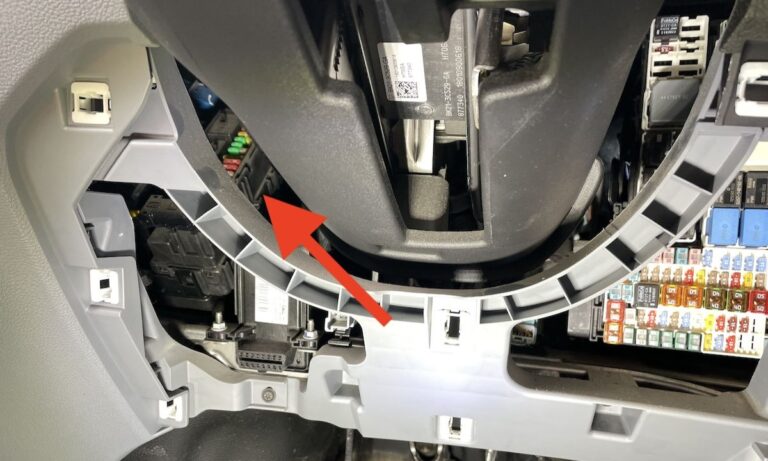
- Passenger compartment: Right passenger footwell behind trim.
- Power Distribution Box: Engine bay, driver’s side.
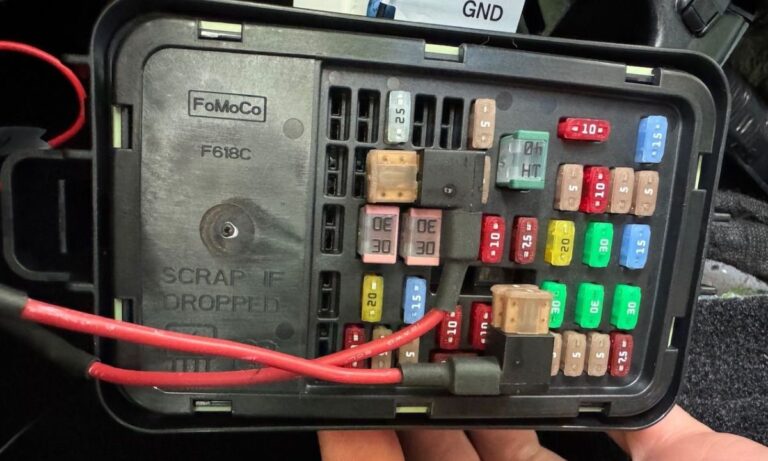
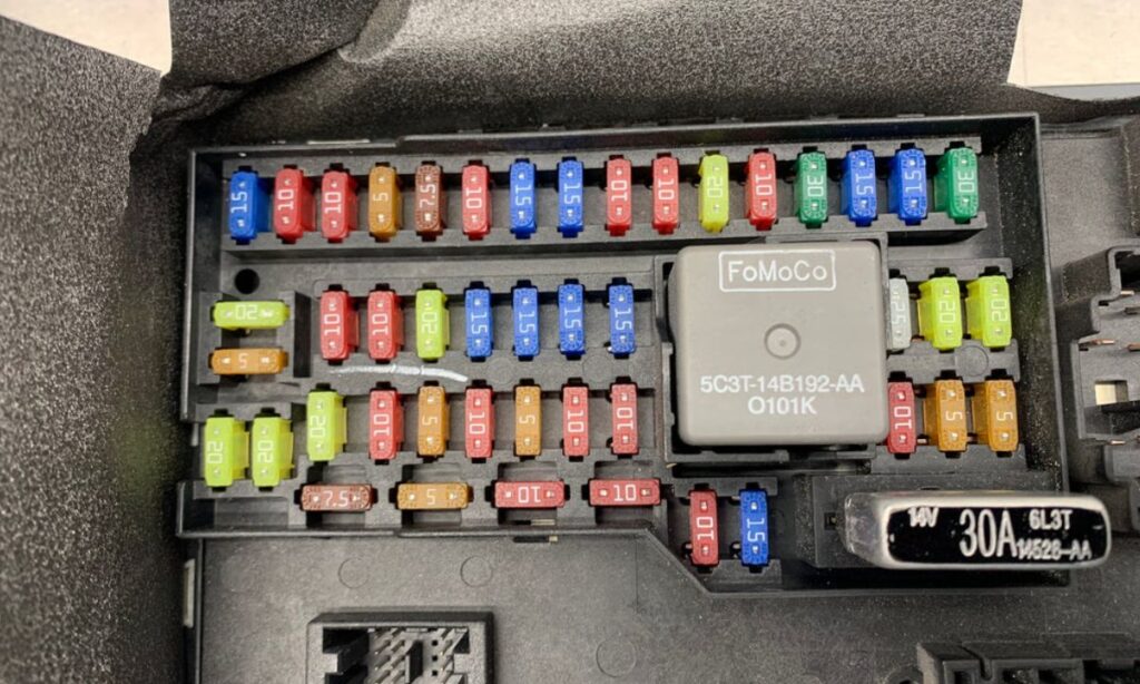
Passenger Compartment Fuse Panel (full list)
| Number | Amperage | Description |
|---|---|---|
| 1 | 10A | Demand lamps / USB |
| 2 | 7.5A | Power exterior mirror |
| 3 | 20A | Driver door unlock |
| 4 | 5A | Not used |
| 5 | 20A | Subwoofer amplifier |
| 12 | 7.5A | Climate control module |
| 13 | 7.5A | Gateway module, steering column, instrument cluster |
| 26 | 30A | Right-hand front window motor |
| 27 | 30A | Amplifier |
| 29 | 30A | Left-hand rear window |
| 30 | 30A | Right-hand rear window |
| 32 | 10A | Remote keyless entry, SYNC, GPS |
| 33 | 20A | Audio head unit |
| 34 | 30A | Run-start bus |
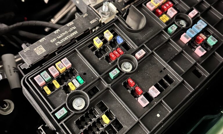
Engine Compartment Power Distribution Box (full key entries)
| Number | Amperage | Description |
|---|---|---|
| 5 | 50A | ABS pump |
| 6 | 50A | Body control module |
| 9 | 40A | Rear defroster |
| 11 | 30A | Left-hand front window |
| 12 | 30A | Driver seat |
| 13 | 30A | Passenger seat |
| 30 | 30A | Starter solenoid |
| 49 | 30A | Fuel pump |
| 60 | 5A | PCM |
7th Generation – S650 (2024–2026, including Dark Horse)
Location:
- Under Hood Fuse Box (BJB / Power Distribution) – engine compartment.
- Body Control Module (BCM) Fuse Box – right passenger footwell.
Under Hood BJB – Complete List (every fuse)
| Fuse | Amp | Protected Component |
|---|---|---|
| 1 | 40A | Body Control Module 1 |
| 2 | 30A | Not used (spare) |
| 3 | 30A | Body Control Module 2 |
| 4 | 40A | Fuel Pump Control Module |
| 5 | 5A | Not used (spare) |
| 6 | 15A | PCM (Vehicle Power 1) |
| 7 | 30A | EVAP, O2 sensors, VCT solenoids (Vehicle Power 2) |
| 8 | 15A | Cooling fan relay, turbo bypass, active grille, A/C, differential pump |
| 9 | 20A | Ignition coils |
| 11 | 30A | Starter motor |
| 13 | 40A | Blower motor |
| 16 | 10A | Luggage compartment lid latch |
| 23 | 5A | ABS module |
| 24 | 10A | PCM + PSCM |
| 28 | 40A | ABS valve |
| 29 | 60A | ABS pump |
| 30 | 30A | Right front seat / DSM |
| 31 | 30A | Left front seat / DSM |
| 32 | 20A | Front power outlet socket |
| 33 | 20A | Auxiliary power point |
| 37 | 20A | Convertible top motor 1 |
| 38 | 30A | HVAC + DSM |
| 41 | 20A | Convertible top motor 2 |
| 50 | 40A | Heated rear window |
| 51 | 10A | Heated exterior mirrors |
| 67 | 20A | 10R80 transmission |
| 68 | 20A | Steering column lock |
| 69 | 30A | Windshield wiper motor |
| 100 | 15A | Left headlight |
| 101 | 15A | Right headlight |
| 120 | 15A | Fuel injectors + PCM |
| 124 | 5A | Rain sensor |
| 130 | 20A | Differential fluid pump (Dark Horse) |
| 137 | 10A | IPMA (cameras) |
| 148 | 5A | Left taillight |
| 149 | 5A | Right taillight |
| 158 | 20A | 10R80 transmission |
| 160 | 10A | OBD connector / gateway module |
| 181 | 5A | Headlamp control module |
| 182 | 30A | Body Control Module |
Body Control Module (BCM) Panel – Complete List
| Fuse | Amp | Protected Component |
|---|---|---|
| 2 | 10A | Power windows |
| 4 | 20A | Amplifier |
| 7 | 10A | Auxiliary body module |
| 8 | 5A | Telematics control unit |
| 9 | 5A | Intrusion sensor / performance parking brake |
| 12 | 7.5A | Climate control module |
| 13 | 7.5A | Steering column + instrument cluster |
| 15 | 15A | SYNC |
| 19 | 10A | Headlamp switch |
| 20 | 10A | Push button ignition |
| 22 | 40A | Vehicle dynamics module |
| 23 | 60A | Driver door module / window |
| 26 | 20A | Passenger door window |
| 29 | 30A | Instrument cluster |
| 31 | 30A | SYNC display + gateway + keyless entry |
| 32 | 20A | Audio unit |
| 35 | 40A | Auxiliary body module |
| 37 | 30A | Auto-dimming mirror + heated steering wheel |
With these complete diagrams, you can troubleshoot any Mustang electrical issue quickly and accurately. Keep your owner’s manual handy, and consider printing the relevant section for your glovebox. Safe driving and happy wrenching!