Ford Fusion, Mondeo and Taurus fuses — complete diagrams of interior and engine bay fuse boxes with full decoding
The electrical system of modern Ford Fusion, Mondeo and Taurus stands out for its complexity and high reliability. Knowing the exact location and purpose of every fuse helps owners quickly diagnose problems, prevent expensive repairs and keep the vehicle in perfect condition. This guide provides detailed fuse box diagrams for these models.
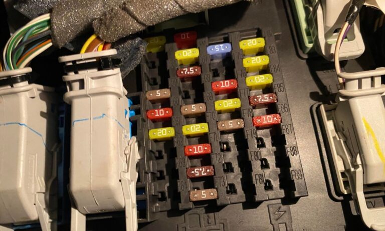
Interior fuse box (passenger compartment)
This block is usually located under the dashboard on the left side of the steering column, behind a decorative cover. It protects comfort systems, lighting, doors, multimedia and auxiliary modules. Here is the complete decoding of positions.
- 1: 10 A — Interior lighting (dome light, glove box, sun visors, trunk).
- 2: 7.5 A — Seat memory, lumbar support, power mirrors.
- 3: 20 A — Driver door unlock.
- 4: 5 A — Reserve.
- 5: 20 A — Subwoofer amplifier.
- 6: 10 A — Heated seat relay.
- 7–9: 10 A — Reserve.
- 10: 5 A — Keyless entry keypad, luggage compartment module.
- 11: 5 A — Reserve.
- 12: 7.5 A — Climate control, gear selector.
- 13: 7.5 A — Steering column, instrument cluster, data link.
- 14: 10 A — Extended power module.
- 15: 10 A — Data gateway module.
- 16: 15 A — Child lock, trunk lid release.
- 17: 5 A — Reserve.
- 18: 5 A — Engine start button.
- 19: 5–7.5 A — Passenger airbag deactivation indicator.
- 20: 5 A — Reserve.
- 21: 5 A — Cabin humidity and temperature sensor.
- 22: 5 A — Occupant classification sensor.
- 23: 10 A — Accessory delay power (power inverter, moonroof).
- 24: 20 A — Central locking.
- 25: 30 A — Driver door (window, mirror).
- 26: 30 A — Passenger door (window, mirror).
- 27: 30 A — Moonroof.
- 28: 20 A — Audio system amplifier.
- 29: 30 A — Rear left door window.
- 30: 30 A — Rear right door window.
- 31: 15 A — Reserve.
- 32: 10 A — Navigation, voice control, display, adaptive cruise.
- 33: 20 A — Radio, active noise cancellation.
- 34: 30 A — Run/start bus feed.
- 35: 5 A — Airbag control module.
- 36: 15 A — Auto-dimming mirror, heated steering wheel.
- 37: 15 A — All-wheel drive, heated steering wheel module.
- 38: 30 A — Reserve.
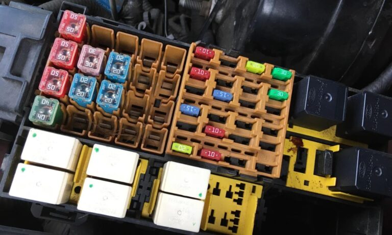
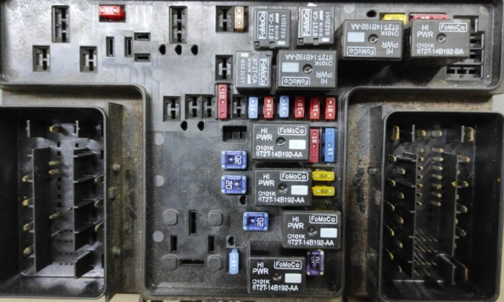
Engine compartment fuse box (upper section)
This powerful distribution box is located in the engine bay, usually near the battery. It protects the engine, fans, starter and high-load circuits. Full diagram with dozens of positions.
- 1: 25–30 A — Windshield wiper motor.
- 2: — — Starter relay.
- 3: 15 A — Auto wipers, rain sensor.
- 4: — — Blower motor relay.
- 5: 20 A — Rear console power outlet.
- 6: — — Reserve.
- 7: 20 A — Powertrain control module (feed 1).
- 8: 20 A — Powertrain control module (feed 2).
- 9: — — Powertrain control module relay.
- 10: 20 A — Driver side power outlet.
- 11–14: 10–15 A — Various engine and ignition circuits.
- 15: — — Run/start relay.
- 16: 20 A — Console power outlet.
- 17–18: 20 A — Reserve.
- 19: 10 A — Electric power steering.
- 20: 10 A — Headlamp startup lighting.
- 21: 15 A — Transmission control.
- 22: 10 A — A/C compressor clutch.
- 23: 15 A — Driver assistance systems (blind spot, camera, cruise).
- 24–28: 10 A — Various auxiliary circuits.
- 29: 5 A — Mass air flow sensor.
- 30–45: 5–20 A — Fan relays, horn, fuel pump, headlights and other systems.
- 46–55: 5–20 A — Generator, brake sensor, horn, engine sensors.
Engine compartment fuse box (Lower power section)
To access this part, release the latches and tilt the box. It contains the highest amperage fuses — up to 60 A — protecting the main vehicle systems.
- 56–57: Reserve.
- 58: 30 A — Fuel pump power.
- 59: 30–40 A — Cooling fan 3.
- 60: 30–40 A — Cooling fan 1.
- 61: Reserve.
- 62: 50 A — Body control module 1.
- 63: 20–30 A — Cooling fan 2.
- 64: 30 A — Reserve.
- 65: 20 A — Front seat heaters.
- 66: Reserve.
- 67: 50 A — Body control module 2.
- 68: 40 A — Rear window defroster.
- 69: 30 A — ABS valves.
- 70: 30 A — Passenger seat power.
- 71: 50 A — Active steering (if equipped).
- 72: 20 A — Transmission oil pump.
- 73: 20 A — Rear seat heaters.
- 74: 30 A — Driver seat module.
- 75: 25 A — Windshield wiper motor 1.
- 76: 30 A — Power liftgate module.
- 77: 30 A — Climate controlled seat module.
- 78: 40 A — Reserve.
- 79: 40 A — Blower motor.
- 80: 25 A — Windshield wiper motor 2.
- 81: 40 A — 110/220 V power inverter.
- 82: 60 A — ABS pump.
- 83: 25 A — Additional circuits.
- 84: 30 A — Starter solenoid.
- 85–87: 20–60 A — Other high-load elements.
Similar diagrams apply to Ford Mondeo and Taurus with minor differences in ratings depending on equipment (hybrid, all-wheel drive, powerful engine). Always check the cover label or owner’s manual for your specific version.
Proper fuse handling increases safety and extends the life of all electronic components. Regularly inspect fuses when you notice issues with lights, power windows or climate control. Replace only with fuses of identical rating to avoid overloading circuits. This knowledge makes ownership of Ford Fusion, Mondeo and Taurus comfortable and predictable in any conditions.