Ford F-150 13th Gen 2014-2020 Fuse Box Guide
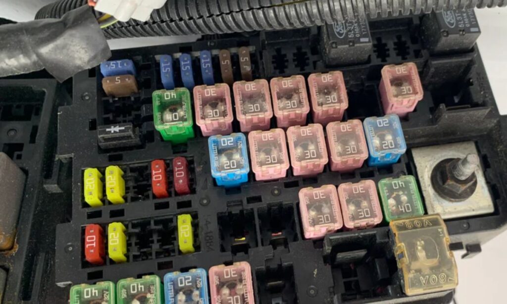
The Ford F-150 thirteenth generation (2014–2020) uses multiple fuse and relay boxes to protect its extensive electrical systems. Understanding the exact location, amperage, and function of every fuse is essential for diagnosing electrical faults, replacing blown fuses correctly, and avoiding damage to sensitive electronics. This guide covers every fuse position in both the passenger compartment fuse box and the engine compartment power distribution box (PDB), along with the auxiliary relay box where applicable, for all variants including the 2.7L EcoBoost, 3.5L EcoBoost, 5.0L V8, and 3.3L V6 engines produced between 2014 and 2020.
Fuse Box Locations on the Ford F-150 (2014–2020)
The 13th generation F-150 has two primary fuse centers:
- Passenger Compartment Fuse Panel – located on the driver’s side lower left of the instrument panel, behind a removable cover.
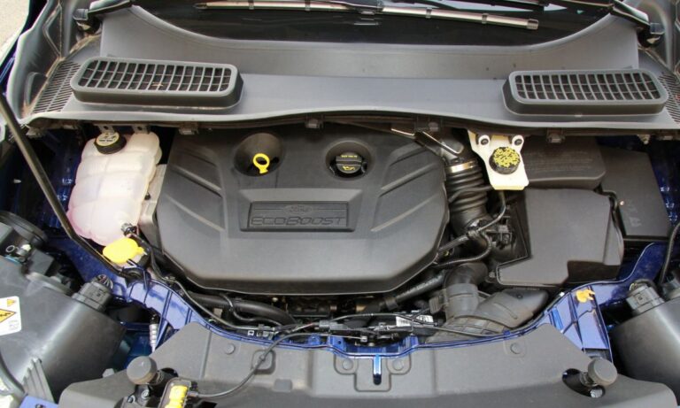
- Engine Compartment Power Distribution Box (PDB) – located in the engine bay on the driver’s side, near the battery, under a snap-off cover labeled with a fuse diagram.
Passenger Compartment Fuse Panel – Complete Fuse List
- F1 – 10A – 4WD switch / terrain management system
- F2 – 10A – Parking aid module / rearview camera
- F3 – 5A – Instrument cluster, message center
- F4 – 10A – Restraints control module (RCM)
- F5 – 10A – Power mirror switch, heated mirrors
- F6 – 20A – Heated/cooled front seats, driver side
- F7 – 20A – Heated/cooled front seats, passenger side
- F8 – 10A – Radio, SYNC infotainment system
- F9 – 10A – APIM (Accessory Protocol Interface Module) / SYNC
- F10 – 10A – Rear view camera module, trailer brake controller
- F11 – 5A – Ambient lighting module
- F12 – 10A – Steering column control module (SCCM)
- F13 – 10A – Body control module (BCM) feed
- F14 – 15A – 12V power outlet, center console
- F15 – 20A – 12V power outlet, rear seat area
- F16 – 20A – Auxiliary 12V outlets, bed / cargo area
- F17 – 10A – Adjustable pedals module
- F18 – 10A – Power running boards module
- F19 – 15A – Front wiper motor (low/high speed)
- F20 – 10A – Rear wiper motor (SuperCrew / SuperCab rear window)
- F21 – 10A – Auto-dimming mirror, rain sensor
- F22 – 10A – Navigation module, GPS antenna
- F23 – 5A – Clock spring / clockspring feed
- F24 – 10A – Driver door module (DDM)
- F25 – 10A – Passenger door module (PDM)
- F26 – 10A – Left rear door module
- F27 – 10A – Right rear door module
- F28 – 15A – Power sliding rear window motor
- F29 – 10A – Keyless entry module, PATS transceiver
- F30 – 5A – Interior lighting, overhead console
- F31 – 10A – Courtesy lamps, door-activated lights
- F32 – 15A – OBD-II diagnostic port (DLC)
- F33 – 10A – Heated steering wheel module
- F34 – 20A – Trailer tow battery charge relay output
- F35 – 10A – Multifunction switch (turn signal, wipers stalk)
Engine Compartment Power Distribution Box – Complete Fuse and Relay List
- PDB F1 – 30A – Anti-lock brake system (ABS) module pump motor
- PDB F2 – 40A – Rear window defroster (electric)
- PDB F3 – 30A – Front blower motor relay output
- PDB F4 – 20A – Engine cooling fan (low speed), radiator fan relay
- PDB F5 – 30A – Engine cooling fan (high speed)
- PDB F6 – 60A – Mega fuse: battery junction box (BJB) feed, main power
- PDB F7 – 40A – Starter motor relay output
- PDB F8 – 20A – Powertrain control module (PCM) keep-alive power
- PDB F9 – 15A – PCM signal feed, throttle body, sensors
- PDB F10 – 10A – Fuel pump relay control
- PDB F11 – 20A – Fuel pump module (direct feed)
- PDB F12 – 15A – Ignition coil pack feed (3.5L EcoBoost / 5.0L V8)
- PDB F13 – 15A – Variable cam timing solenoids (VCT)
- PDB F14 – 10A – Mass airflow sensor (MAF), intake air temp sensor
- PDB F15 – 20A – Transmission control module (TCM) / 6R80 / 10R80 feed
- PDB F16 – 15A – 4WD transfer case control module (TCCM)
- PDB F17 – 10A – Horn relay output
- PDB F18 – 15A – Daytime running lamps (DRL) module
- PDB F19 – 10A – Brake shift interlock solenoid
- PDB F20 – 20A – Trailer tow 7-pin connector (running lamps)
- PDB F21 – 30A – Trailer tow 7-pin connector (brake output)
- PDB F22 – 40A – Rear electric locker / e-locking rear differential
- PDB F23 – 20A – Headlamp switch, exterior lighting control module
- PDB F24 – 15A – LED headlamp module (if equipped)
- PDB F25 – 10A – Fog lamp relay, front fog lamps
- PDB F26 – 20A – Power running boards motor relay
- PDB F27 – 30A – Rear air suspension compressor (if equipped)
- PDB F28 – 40A – Generator / alternator exciter and sense circuit
- PDB F29 – 50A – Mega fuse: body control module (BCM) main feed
- PDB F30 – 15A – Oxygen sensors (upstream and downstream banks)
Important Fuse Ratings and Replacement Notes
- Always use blade-type (ATO/ATC) fuses of the exact rated amperage – never substitute a higher-rated fuse.
- Mega fuses (40A–60A) in the PDB require a flat-blade screwdriver to remove and must only be replaced with identical Ford-specification fuses.
- The F-150 uses mini (APM), standard (ATO), and maxi (APX) fuse types depending on location – check the cover diagram before purchasing replacements.
- A blown F32 (OBD-II port fuse) will prevent scan tool communication – always check this fuse first when a scanner shows no communication.
- On 2017–2020 models with the 10R80 10-speed transmission, PDB F15 is especially critical – a blown fuse here triggers a no-start or transmission fault condition.
- The BCM fuse (PDB F29, 50A) controls a wide range of comfort and safety features; replacement requires clearing fault codes with a scan tool after repair.
- When adding aftermarket accessories to the auxiliary 12V circuits (F15, F16), total load must not exceed 20A per circuit.
How to Identify a Blown Fuse on the Ford F-150
- Remove the fuse with the plastic fuse puller tool stored inside the passenger compartment fuse panel cover.
- Inspect the metal strip inside the fuse body – a broken or melted bridge confirms it is blown.
- Use a 12V test light or multimeter set to continuity/voltage to verify under-load conditions before replacing.
- If a fuse blows repeatedly, do not replace with a higher amperage fuse – diagnose the underlying short circuit or overloaded component first.