Toyota Sienna XL40 2020+ Fuses: Complete Guide
The Toyota Sienna XL40, introduced for the 2021 model year (sold as 2020+ in some markets), features a completely redesigned electrical architecture compared to its predecessor. This fourth-generation Sienna is exclusively offered as a hybrid, which means its fuse layout is more complex than earlier generations, incorporating both a standard 12V accessory battery circuit and a high-voltage hybrid system. Understanding the exact fuse locations, amperage ratings, and functions is essential for diagnosing electrical faults, replacing blown fuses safely, and avoiding costly dealer visits for simple issues.
Fuse Box Locations on the Toyota Sienna XL40
The Toyota Sienna XL40 has three primary fuse and relay box locations:
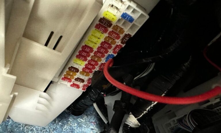
- Instrument Panel Fuse Block (Driver Side) – Located under the dashboard on the driver’s side, accessible by removing the lower trim panel.
- Engine Compartment Fuse Block – Located in the engine bay, typically on the left (driver’s) side near the firewall, under a protective cover.
- Rear Auxiliary Fuse Block – Located under the rear passenger area or in the cargo compartment, relevant for rear entertainment and power outlets.
Instrument Panel Fuse Block – Driver Side
This block controls cabin electronics, convenience features, and safety systems. Always turn off the ignition before accessing this box.
- 1 – 10A – Power window master switch (driver)
- 2 – 10A – Door lock/unlock control module
- 3 – 7.5A – Combination meter / instrument cluster
- 4 – 10A – SRS airbag system ECU
- 5 – 10A – Brake light switch / stop lamp circuit
- 6 – 7.5A – Body control module (BCM) primary feed
- 7 – 10A – Keyless entry / smart key receiver
- 8 – 7.5A – Interior courtesy lights
- 9 – 10A – Rear wiper and washer motor
- 10 – 15A – Heated steering wheel
- 11 – 20A – Front power windows (passenger side)
- 12 – 20A – Front power windows (driver side)
- 13 – 10A – Sliding door motor control (left)
- 14 – 10A – Sliding door motor control (right)
- 15 – 10A – Rear gate / power back door ECU
- 16 – 7.5A – HVAC blower motor relay signal
- 17 – 10A – Audio / multimedia head unit
- 18 – 10A – Navigation / display audio backup power
- 19 – 7.5A – OBD-II diagnostic port (DLC3)
- 20 – 10A – Parking assist / rear camera module
- 21 – 10A – Blind spot monitoring (BSM) system
- 22 – 10A – Pre-collision system (PCS) ECU
- 23 – 7.5A – Lane departure alert system
- 24 – 10A – Cruise control / radar cruise module
- 25 – 15A – Power outlet (12V accessory socket, front)
- 26 – 15A – Cigarette lighter / front accessory socket
- 27 – 20A – Power seat (driver, fore/aft and recline)
- 28 – 20A – Power seat (passenger)
- 29 – 10A – Mirror adjustment / fold motors
- 30 – 15A – Heated seats (front)
- 31 – 15A – Ventilated seats (front)
- 32 – 10A – Rear HVAC control panel (second row)
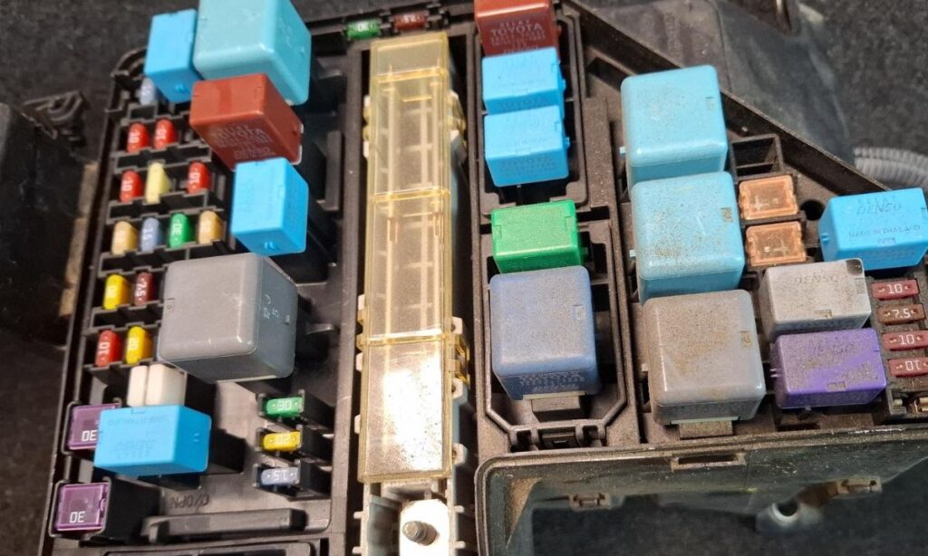
Engine Compartment Fuse and Relay Block
This block handles high-current loads for under-hood components and major vehicle systems. Fuses here are typically ATO/ATC blade or JCASE cartridge type.
- 1 – 120A – Main battery fuse (12V auxiliary battery feed to vehicle systems)
- 2 – 80A – Electric power steering (EPS) motor
- 3 – 60A – HVAC blower motor main feed
- 4 – 50A – Anti-lock brake system (ABS) / VSC actuator pump
- 5 – 40A – Hybrid system cooling fan motor
- 6 – 30A – Engine cooling fan motor (electric)
- 7 – 30A – DC-DC converter protection fuse (hybrid auxiliary charging)
- 8 – 30A – Inverter cooling pump circuit
- 9 – 20A – Headlamp relay feed (low/high beam)
- 10 – 20A – Front fog lamps
- 11 – 15A – Daytime running lights (DRL) control
- 12 – 10A – Hybrid ECU (HV ECU) primary signal fuse
- 13 – 10A – Engine management ECU (main feed, ICE portion)
- 14 – 10A – Transmission control / transaxle ECU (THS-II)
- 15 – 15A – Horn
- 16 – 20A – Windshield wiper motor
- 17 – 20A – Windshield washer pump and heated washer system
- 18 – 10A – Throttle body actuator
- 19 – 10A – Oxygen sensors / exhaust gas sensors
- 20 – 15A – Fuel system (vapor canister purge, VSV)
- 21 – 30A – Rear 120V AC power outlet inverter (if equipped)
- 22 – 20A – AWD e-axle motor controller (AWD models)
- 23 – 10A – VDIM / traction control ECU signal
Rear Auxiliary Fuse Block
- 1 – 20A – Rear power outlet (12V, second/third row)
- 2 – 15A – Rear entertainment system / rear-seat display screens
- 3 – 10A – Rear USB charging ports (second and third row)
- 4 – 10A – Rear HVAC blower (third row)
- 5 – 15A – Power sliding door window regulators (rear)
Fuse Types Used in the Sienna XL40
- Mini ATM / low-profile mini fuses – Used extensively in interior panel blocks; identified by their small footprint.
- Standard ATO/ATC blade fuses – Used for medium-current loads in engine bay and interior blocks.
- JCASE cartridge fuses – Used for high-current circuits such as EPS, blower, and ABS; do not confuse with standard blade fuses.
- Bolt-type fusible links – Used for the 120A main battery fuse; require professional replacement.
Important Safety Notes for Hybrid Models
- Never attempt to access or modify the orange high-voltage cabling or the HV battery fuse service plug without proper hybrid safety training.
- Always use the READY OFF state and wait a minimum of 5 minutes for HV capacitors to discharge before working near hybrid components.
- Replace fuses only with identical amperage ratings; upsizing a fuse can cause wiring fires.
- A repeatedly blown fuse in the same circuit indicates an underlying short circuit — do not simply replace and ignore.
- Use a fuse puller tool (included in the driver-side fuse block) to avoid bending pins or touching live metal.