Toyota Camry XV70 Fuses: Complete Guide & Diagram 2017+
The Toyota Camry XV70 (2017 and later) uses multiple fuse boxes to protect the electrical systems throughout the vehicle. Understanding the location, rating, and function of every fuse is essential for diagnosing electrical faults, replacing blown components, and performing safe modifications. This guide covers every fuse in each box of the XV70 Camry, including the engine compartment fuse block, the instrument panel fuse box, and the additional relay/fuse centers introduced on this generation.
Fuse Box Locations on the Toyota Camry XV70
The XV70 Camry has three primary fuse and relay centers:
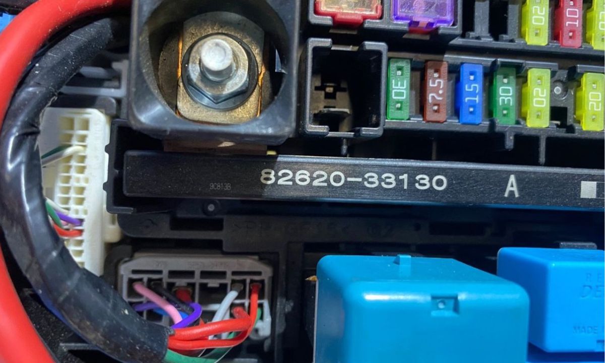
- Engine Compartment Fuse Block – located on the left side of the engine bay, near the battery
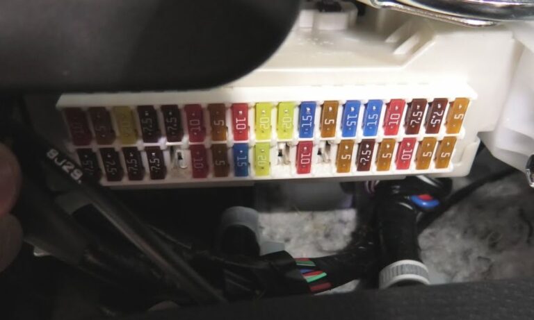
- Instrument Panel Fuse Box (Driver Side) – behind the lower trim panel on the driver’s left knee area
- Engine Room Relay Block No. 2 – a secondary block also in the engine bay, adjacent to the main block
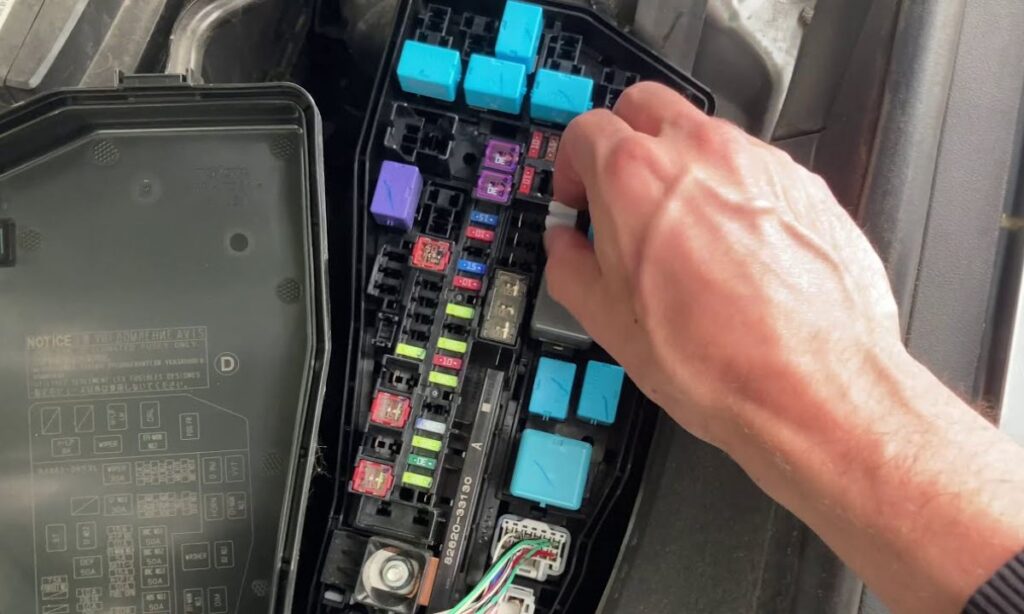
Engine Compartment Fuse Block – Complete Fuse List
- ALT Fuse 120A – Alternator charge circuit
- AM1 Fuse 80A – Main battery supply line No. 1
- AM2 Fuse 60A – Main battery supply line No. 2
- EFI Fuse 30A – Engine fuel injection and engine management system
- IG1 Fuse 40A – Ignition switch power supply No. 1
- IG2 Fuse 30A – Ignition switch power supply No. 2
- HTR Fuse 40A – Heater blower motor
- ABS No.1 Fuse 40A – ABS/VSC hydraulic control unit motor
- ABS No.2 Fuse 30A – ABS/VSC actuator and ECU power supply
- ECU-B Fuse 20A – ECU battery-direct supply, memory keep-alive
- EPS Fuse 50A – Electric power steering motor
- FAN No.1 Fuse 40A – Cooling fan relay and motor No. 1
- FAN No.2 Fuse 30A – Cooling fan motor No. 2 / condenser fan
- MAIN Fuse 120A – Primary fusible link protecting entire vehicle electrical system
- RDI Fuse 20A – Radar / Pre-collision system sensor
- STOP Fuse 15A – Brake light switch and stop lamp circuit
- CDS Fuse 10A – Air conditioning compressor clutch or electronic control
- HORN Fuse 15A – Horn relay and horn
- DOME Fuse 10A – Interior dome lights, door courtesy lights
- TAIL Fuse 15A – Tail lamps, license plate lamps, parking lamps
- HEAD LH Fuse 15A – Left-hand headlamp low/high beam
- HEAD RH Fuse 15A – Right-hand headlamp low/high beam
- FOG Fuse 15A – Front fog lamp relay circuit (where fitted)
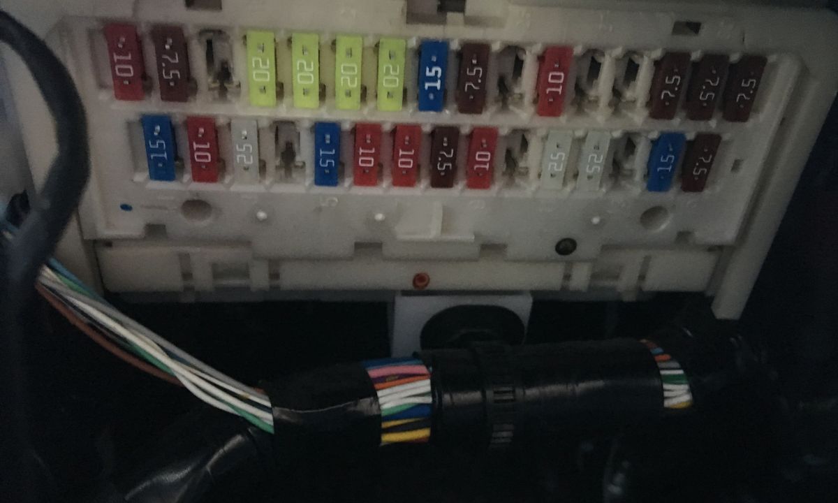
Instrument Panel (Interior) Fuse Box – Complete Fuse List
- Fuse 1 – 7.5A – Combination meter, speedometer cluster
- Fuse 2 – 15A – Power window master switch (driver), window lock
- Fuse 3 – 20A – Power window motor, rear windows
- Fuse 4 – 7.5A – Audio system, multimedia head unit
- Fuse 5 – 10A – Navigation system, display audio
- Fuse 6 – 15A – OBD-II diagnostic port, data link connector
- Fuse 7 – 7.5A – Theft deterrent system, immobiliser ECU
- Fuse 8 – 10A – Door lock actuators, keyless entry receiver
- Fuse 9 – 15A – Cigarette lighter / accessory socket No. 1
- Fuse 10 – 20A – Accessory socket No. 2 (centre console)
- Fuse 11 – 7.5A – SRS airbag ECU power supply
- Fuse 12 – 10A – Rear defroster relay coil
- Fuse 13 – 30A – Rear defroster heater grid
- Fuse 14 – 10A – Mirror heater, heated mirror control
- Fuse 15 – 7.5A – Lane departure alert system, LDA camera
- Fuse 16 – 10A – Reverse camera, back-up camera system
- Fuse 17 – 5A – Clock, radio memory, TCM memory keep-alive
- Fuse 18 – 10A – Instrument panel illumination, dimmer control
- Fuse 19 – 15A – Windshield wiper motor and washer pump
- Fuse 20 – 10A – Turn signal lamps, hazard warning flasher
- Fuse 21 – 10A – Seat heater switch and relay (front seats)
- Fuse 22 – 20A – Seat heater element circuits
- Fuse 23 – 10A – HVAC control panel, blower speed controller
- Fuse 24 – 15A – Power seat motor (driver, fore-aft and recline)
- Fuse 25 – 7.5A – Blind spot monitoring (BSM) ECU
- Fuse 26 – 10A – USB charging ports, USB data hub
- Fuse 27 – 10A – Bluetooth module, telematics (where fitted)
- Fuse 28 – 7.5A – Parking sensor ECU (RCTA / PKSB)
How to Identify and Replace a Blown Fuse
Always turn the ignition OFF before inspecting or replacing a fuse. Use the plastic fuse puller stored inside the fuse box lid. A blown fuse will show a melted or broken wire element visible through the transparent body. Replace only with a fuse of the identical amperage rating – never use a higher-rated fuse as this can cause wiring fires. The XV70 Camry uses standard ATO/ATC blade fuses throughout the instrument panel box, while the engine bay uses both blade and large JCase/MCASE cartridge fuses for the high-current circuits.
Common Electrical Faults and Associated Fuses on the XV70 Camry
- OBD port not powering scan tool – check Fuse 6 (15A) in instrument panel box
- Cigarette lighter / USB not working – check Fuses 9, 10, and 26 in instrument panel box
- Rear defroster inoperative – check Fuses 12 and 13 in instrument panel box
- Power windows inoperative – check Fuses 2 and 3 in instrument panel box and IG2 fuse in engine bay
- No crank / no start – check AM1, AM2, and IG1 fuses in the engine compartment block
- Pre-collision system warning light – check RDI fuse (20A) in engine compartment
- Electric power steering warning – check EPS fuse (50A) in engine compartment
- Headlamps not working – check HEAD LH and HEAD RH fuses (15A each) in engine compartment
Important Notes for the Toyota Camry XV70 Fuse System
- The 2018 and later facelifts share the same fuse layout as the 2017 launch model; no changes were made to fuse ratings
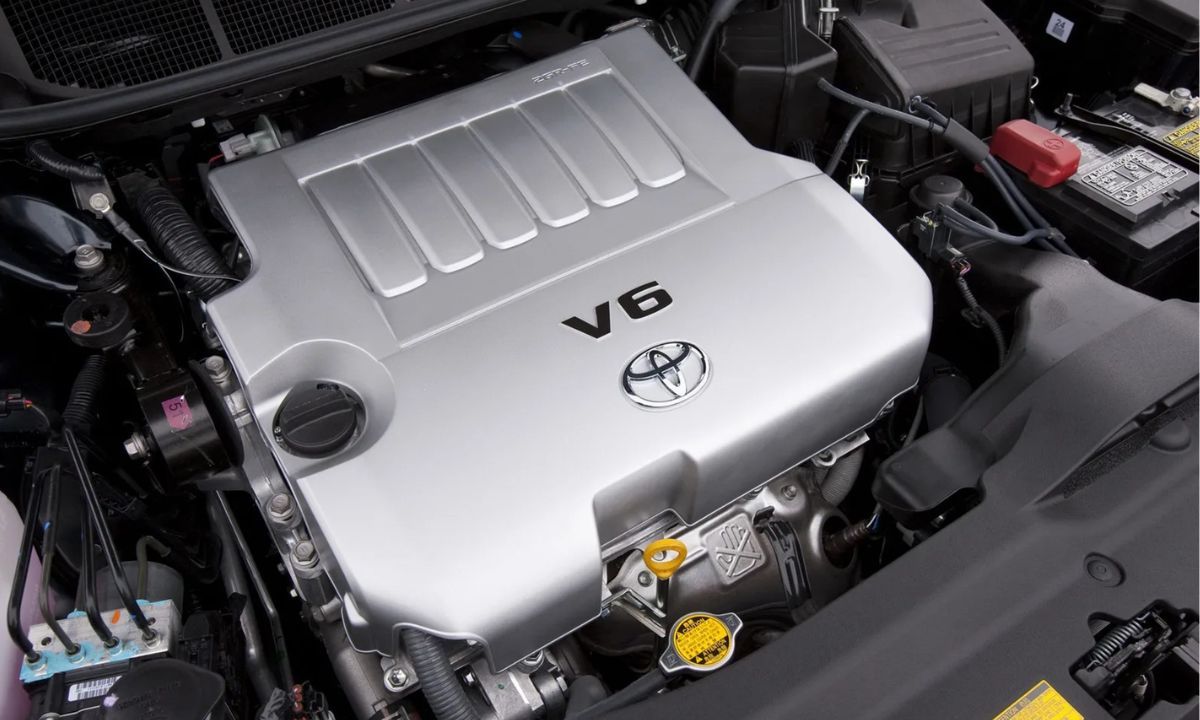
- Hybrid variants (XV70h) include additional fuses for the HV battery cooling fan and hybrid ECU within the engine bay block – always consult the hybrid-specific wiring diagram
- The 120A MAIN fusible link is not serviceable with a standard blade fuse – it requires a genuine Toyota OEM cartridge fuse
- Always carry spare 10A and 15A blade fuses in the glovebox; these cover the most commonly blown circuits
- After replacing a repeatedly blown fuse, diagnose the root cause (short circuit, overloaded accessory, water ingress) before inserting a new fuse