Toyota Avalon XX40 Fuses: Complete Guide 2012-2018
The Toyota Avalon XX40, produced from 2012 to 2018, uses a multi-box fuse and relay system to protect all electrical circuits across the vehicle. Understanding the exact fuse layout, amperage ratings, and circuit assignments is essential for diagnosing electrical faults, replacing blown fuses correctly, and avoiding accidental short circuits. This guide covers every fuse box location in the XX40 Avalon, lists all fuses with their precise amperage and function, and provides practical guidance for maintenance and troubleshooting.
Fuse Box Locations in the Toyota Avalon XX40
The XX40 Avalon has three primary fuse and relay box locations:
- Engine Compartment Fuse Box (Main Relay Box) – located on the driver’s side of the engine bay, near the battery
- Instrument Panel Fuse Box (Driver’s Side) – located beneath the dashboard on the driver’s side, accessible by removing the lower cover panel
- Passenger Side Junction Box – located under the dashboard on the passenger side, primarily serving secondary systems
Engine Compartment Fuse Box – Full Fuse List
This box handles high-current circuits and major powertrain and safety systems. All fuses listed below apply to 2012–2018 Toyota Avalon XX40 unless otherwise noted.
- ALT – 120A – Alternator charge circuit
- AM1 – 80A – Battery positive main feed to ignition switch
- AM2 – 60A – Battery positive feed to instrument panel junction
- EFI – 30A – Electronic fuel injection system
- HTR – 40A – Heater and air conditioning blower motor
- RDI – 30A – Radiator cooling fan relay circuit
- ABS – 40A – Anti-lock braking system motor and pump
- ST – 30A – Starter motor relay circuit
- ECU-B – 15A – ECU backup power supply
- CDS FAN – 30A – Condenser fan motor
- EPS – 80A – Electric power steering system
- HORN – 15A – Horn relay and circuit
- DOME – 15A – Interior dome and map lights
- TAIL – 15A – Tail and parking lights
- HAZ – 10A – Hazard warning flasher circuit
- STOP – 10A – Brake light switch and stop lamp circuit
- TURN – 10A – Turn signal indicator circuit
- GAUGE – 10A – Instrument cluster and gauges
- FOG – 15A – Front fog light relay
- MIR HTR – 10A – Heated exterior mirrors
- DEF – 40A – Rear window defogger
- PWR OUTLET – 15A – 12V accessory power outlet
- AM3 – 7.5A – Ignition key-on accessory feed
Instrument Panel Fuse Box (Driver’s Side) – Full Fuse List
This box is the main distribution point for interior, infotainment, and body control circuits. It is accessed by pulling down the trim panel beneath the steering column.
- CIG – 15A – Cigarette lighter / accessory socket
- OBD – 7.5A – OBD-II diagnostic port power
- ECU-IG – 10A – Engine control unit ignition feed
- TCM – 10A – Transmission control module
- SRS – 10A – Supplemental restraint system (airbags)
- ABS/VSC – 10A – ABS and vehicle stability control ECU
- ETCS – 10A – Electronic throttle control system
- WIPER – 20A – Front windshield wiper motor
- WASHER – 10A – Windshield washer pump
- POWER WINDOW – 20A – All power window motors and master switch
- DOOR LOCK – 20A – Central door lock actuators
- MIRROR – 10A – Power mirror adjustment motors
- SEAT HTR – 20A – Heated front seat elements
- SEAT – 20A – Power seat adjustment motors
- AUDIO – 10A – Audio head unit and amplifier
- NAV – 10A – Navigation and display system
- CAMERA – 10A – Backup camera system
- ACC – 7.5A – Accessory relay switched power
- IG1 – 7.5A – Ignition switch position 1 feed
- IG2 – 7.5A – Ignition switch position 2 feed
- DOME – 10A – Dome light and courtesy lamps
- PANEL – 5A – Instrument panel backlighting
- METER – 7.5A – Speedometer and instrument cluster feed
- TURN SIG – 10A – Turn signal relay
- HAZ – 10A – Hazard flasher relay circuit (secondary)
- CLOCK – 7.5A – Clock and memory keep-alive circuit
- SMART KEY – 7.5A – Smart key system ECU (if equipped)
- CRUISE – 10A – Adaptive cruise control module
- HTD STR – 10A – Heated steering wheel (if equipped)
- A/C – 10A – Air conditioning control panel
- BLOWER – 30A – Blower motor resistor circuit (cabin)
Passenger Side Junction Box – Full Fuse List
- SUB WOOFER – 10A – Subwoofer amplifier circuit (JBL trim)
- AMP – 10A – External audio amplifier feed (premium audio)
- BSM – 10A – Blind spot monitoring system (if equipped)
- PARK ASST – 10A – Parking assist sensor system
- LANE DEP – 10A – Lane departure alert system (if equipped)
- TPMS – 10A – Tire pressure monitoring system ECU
- USB – 5A – USB charging and data port
- ILLUM – 5A – Ambient interior illumination
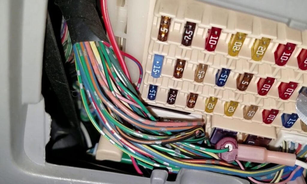
How to Identify and Replace a Blown Fuse
A blown fuse in the XX40 Avalon typically causes a complete loss of function in a specific system. To inspect fuses:
- Turn the ignition off before accessing any fuse box
- Use the fuse puller tool stored inside the engine bay fuse box lid
- Visually inspect the fuse element – a broken wire inside the plastic body indicates a blown fuse
- Always replace with the exact same amperage rating – never use a higher-rated fuse as a substitute
- If a fuse blows repeatedly, a short circuit or overloaded component is the cause – do not keep replacing without diagnosing the fault
- Toyota Avalon XX40 uses standard ATO/ATC blade-type fuses for most positions and MCASE/JCASE cartridge fuses for high-amperage circuits in the engine bay
Common Electrical Issues by Fuse Circuit
- WIPER fuse (20A) – fails due to wiper motor overload in icy conditions
- POWER WINDOW fuse (20A) – blown when a window regulator seizes
- SRS fuse (10A) – if blown, airbag warning light illuminates and system is disabled
- EFI fuse (30A) – engine may crank but not start if this fuse fails
- ABS fuse (40A) – ABS and traction control warning lights activate simultaneously