Honda Civic 9th Gen Fuses: Complete Guide 2011-2015
The Honda Civic 9th generation (2011-2015) uses two primary fuse boxes to protect every electrical circuit in the vehicle. Understanding the exact location, amperage, and function of each fuse is essential for diagnosing electrical failures, replacing blown fuses safely, and avoiding damage to sensitive electronics. This guide covers every fuse in both the under-hood fuse box and the interior fuse box, along with relay positions and practical troubleshooting advice specific to the FB, FG, and FG2 body styles sold globally.
Fuse Box Locations on the 2011-2015 Honda Civic
The 9th gen Civic has two fuse and relay boxes:
- Under-Hood Fuse Box (Engine Compartment) – located on the driver’s side of the engine bay, near the battery. It contains high-amperage fuses and main relays.
- Interior Fuse Box (Passenger Compartment) – located beneath the driver’s side dashboard, to the left of the steering column. It contains low-to-medium amperage fuses protecting cabin and accessory circuits.
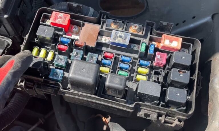
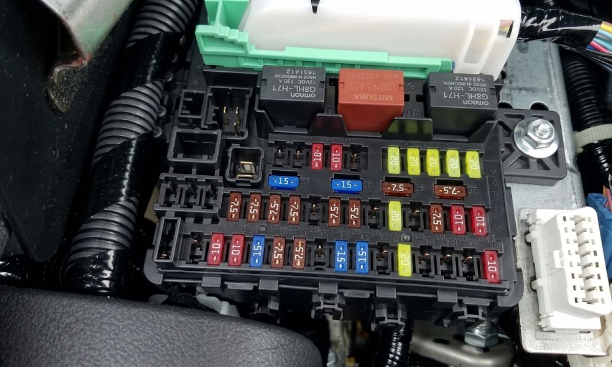
Under-Hood Fuse Box – Complete Fuse List
The following fuses are found in the engine compartment box. Always disconnect the negative battery terminal before replacing high-amperage fuses.
- F1 – 120A – Main fuse (battery to under-hood fuse box)
- F2 – 80A – ABS motor
- F3 – 40A – Starter cut relay / ignition switch
- F4 – 40A – ABS unit (solenoid)
- F5 – 40A – Blower motor relay
- F6 – 30A – Power windows (master switch circuit)
- F7 – 30A – Charging system / alternator output
- F8 – 20A – Radiator fan relay (main fan)
- F9 – 20A – Condenser fan relay
- F10 – 20A – Fuel pump relay output
- F11 – 15A – Injector relay / engine management power
- F12 – 15A – PCM (Powertrain Control Module) main power
- F13 – 15A – Ignition coils
- F14 – 10A – Engine sensors (MAP, IAT, CKP)
- F15 – 10A – ECT sensor, VTC solenoid
- F16 – 10A – Purge control solenoid / EVAP system
- F17 – 10A – EGR / idle control (where applicable)
- F18 – 7.5A – PCM backup / KAM (keep-alive memory)
- F19 – 7.5A – Starter relay coil circuit
- Relay 1 – Main relay (fuel pump + PCM)
- Relay 2 – Fan relay (high speed)
- Relay 3 – Fan relay (low speed)
- Relay 4 – A/C compressor clutch relay
- Relay 5 – Starter cut relay
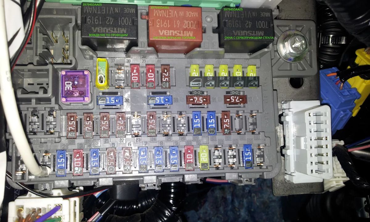
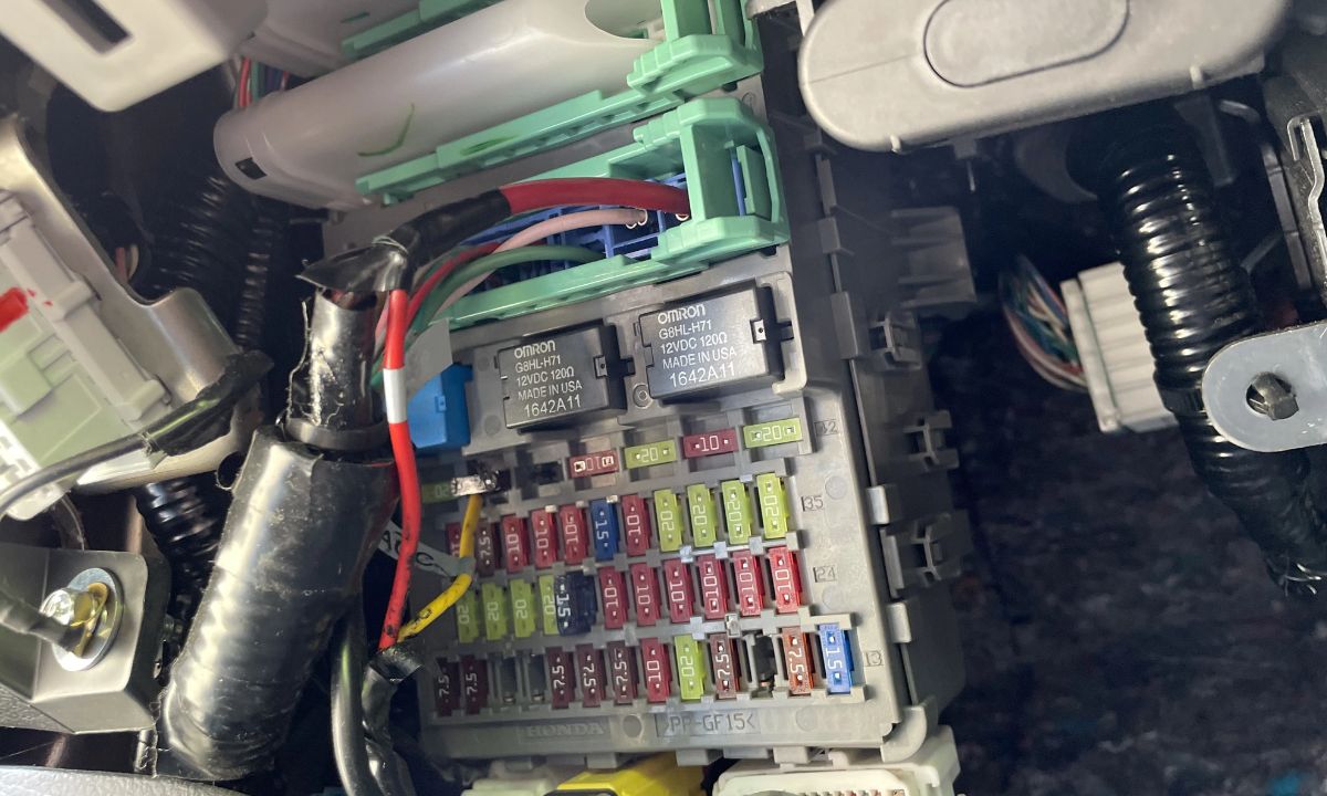
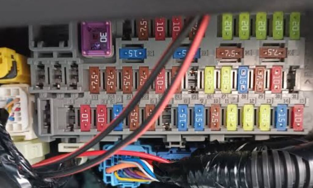
Interior (Dashboard) Fuse Box – Complete Fuse List
The interior fuse box is accessible by removing the lower panel beneath the driver’s side dash. A fuse puller tool is stored inside the lid.
- No.1 – 7.5A – Keyless entry / immobilizer unit
- No.2 – 7.5A – Instrument cluster illumination / gauge backlight
- No.3 – 7.5A – Audio system (radio) memory
- No.4 – 7.5A – Clock / cabin lighting memory
- No.5 – 10A – Interior lights (dome, map, courtesy lights)
- No.6 – 10A – Turn signal / hazard lights relay circuit
- No.7 – 10A – Brake lights
- No.8 – 10A – Backup lights (reverse lamps)
- No.9 – 10A – Horn
- No.10 – 10A – Windshield wipers (low / high)
- No.11 – 10A – Windshield wiper washer pump
- No.12 – 10A – Daytime running lights (DRL, Canada/export)
- No.13 – 15A – Cigarette lighter / accessory socket
- No.14 – 15A – Power mirrors (folding and adjustment)
- No.15 – 15A – Power door locks (actuators)
- No.16 – 15A – Heated rear window (defroster)
- No.17 – 15A – Sunroof / moonroof motor (where equipped)
- No.18 – 20A – Front power windows (driver and passenger)
- No.19 – 20A – Rear power windows (where equipped)
- No.20 – 20A – Blower motor (HVAC fan)
- No.21 – 20A – A/C controls and compressor relay circuit
- No.22 – 20A – Audio system (amplifier / head unit power)
- No.23 – 20A – Seat heater (driver side, where equipped)
- No.24 – 20A – Seat heater (passenger side, where equipped)
- No.25 – 10A – Steering angle sensor / VSA system
- No.26 – 10A – TPMS module (tyre pressure monitoring, where equipped)
- No.27 – 10A – Navigation / infotainment screen (where equipped)
- No.28 – 10A – Rear camera / parking sensors (where equipped)
- No.29 – 7.5A – OBD-II diagnostic port (DLC3 power)
- No.30 – 7.5A – Combination switch (wiper stalk, turn signal stalk)
Fuse Specifications and Types Used
- Blade fuse types: Mini (ATC/ATM) for interior box; Regular (ATC) and maxi/cartridge for engine bay
- Colour coding: 7.5A = Brown, 10A = Red, 15A = Blue, 20A = Yellow, 30A = Green, 40A = Orange, 80A = Black cartridge, 120A = Red cartridge
- Always replace with identical amperage – never use a higher-rated fuse as a substitute
- Honda recommends Littelfuse or equivalent OEM blade fuses for the 9th gen Civic
How to Identify a Blown Fuse
- Visually inspect the metal strip inside the transparent plastic body – a broken or melted strip confirms a blown fuse
- Use a test light or multimeter on both terminals of the fuse while it is seated to verify power flow
- A circuit with no power and a visually intact fuse may indicate a faulty relay or wiring fault, not the fuse itself
- Repeated blown fuses on the same circuit indicate a short to ground – do not continue replacing without diagnosing the root cause
Common Electrical Issues by Fuse Circuit – 9th Gen Civic
- No.13 (15A cigarette lighter) – commonly blown by USB adapters or accessories drawing excessive current; check accessory wattage
- No.10 (10A wipers) – may blow if wiper blades freeze to screen and motor stalls; always clear ice before use
- F6 (30A power windows) – can blow if window runs against an obstruction or regulator seizes; lubricate window channels annually
- No.20 (20A blower motor) – common fault on 2012-2013 models due to blower motor resistor failure before fuse blows
- F2 (80A ABS) – if blown, ABS and VSA warning lights will illuminate; requires immediate inspection
- No.29 (7.5A OBD-II port) – if scan tool shows no communication, check this fuse first before assuming ECU failure